HRTIM Master
Purpose
Synchronize multiple high resolution timer (HRTIM) timing units to generate frequency and/or phase variable PWM signals
Library
STM32
Description

The HRTIM Master block allows the synchronization of multiple HRTIM Timing Unit blocks. This synchronization enables the generation of frequency variable and/or phase shifted PWM output signals.
All synchronized HRTIM timing units will inherit the configured carrier frequency. The carrier frequency can be controlled by using the scalar input signal \(f'\). The resulting carrier frequency \(f_\mathrm{c}\) is calculated as the product of the nominal carrier frequency specified in the block parameter Carrier frequency and the input signal \(f'\).
An additional enable input terminal \(en\) can be activated. Applying a signal \(=0\) to this port will set all synchronized HRTIM timing units to their idle state.
The HRTIM Master block can also be used as burst mode controller. Burst mode operation is commonly used during light load conditions to increase the converter efficiency. It allows to have the output channels of synchronized HRTIM timing units alternatively in idle and run state, by hardware. Due to this, some switching periods can be skipped with configurable periodicity and variable duty cycle. The burst mode duty cycle can be set by the \(Bd\) input terminal and has to be a value between \(0\) and \(1\), as shown in the figure below.
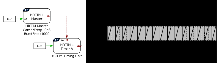
Fig. 17 Burst mode controller with a burst mode duty cycle of 0.4.
The HRTIM master block can configure interrupts to trigger the ADC start-of-conversion and the Control Task Trigger. Interrupts are synchronized with the PWM carrier, and the repetition counter period determines how many events need to occur before a trigger is generated. Trigger events will always occur at the period event (overflow) of the sawtooth carrier.
Note
The HRTIM Master block employs preload and shadow registers to manage updates to the period. When the CPU writes a new period value, it is first stored in a preload register. The value is then transferred to the shadow register when an update event occurs.
The event that performs this transfer is the same event that is used to trigger the base task and is configured in the Trigger tab. It typically occurs at the end of a period or in the middle of a period and can be downsampled by a repetition counter. The HRTIM peripheral uses the values stored in the shadow register, ensuring that the period update takes effect only at the defined updated event.
Parameters
Main
- HRTIM unit
Selects the HRTIM timer unit to use.
- Carrier frequency
Defines the frequency of the carrier in hertz \((\mathrm{Hz})\). The HRTIM master carrier is always of type sawtooth.
- Frequency tolerance
Specifies the behavior when the desired carrier frequency is not achievable based on the system clock frequency.
- Frequency variation
Enables or disables the frequency input port \(f'\). The resulting output frequency of all synchronized HRTIM timing units is given by \(f'\) multiplied by the Carrier frequency parameter.
- Variable frequency lower limit
The HRTIM prescaler is configured during MCU initialization and cannot be modified during operation. To prevent saturation of the period register during runtime, a lower bound must be defined for the operating range of the input to the frequency variation inport
f'. It is defined per unit \((\mathrm{pu})\) of the nominal frequency. This lower bound is used to select the HRTIM prescaler and defines the frequency range guaranteed during operation. The minimum achievable frequency during operation may be lower than this bound, as it is determined by the selected prescaler.- Enable port
An additional component port is created if Enable port is set to
Show. Applying a signal \(= 0\) to this port sets all synchronized HRTIM timing unit output channels to their idle state.- Synchronization
If set to
Self, the HRTIM Master is not synchonized to any external signals.If set to
External, the HRTIM Master block is synchonized to an external signal using an External Sync block. If the Synchronization behavior of the External Sync block is set toStart and reset on sync, the Carrier frequency of the HRTIM Master block is restricted to a range of frequencies or even a particular set of discrete frequencies. The restrictions on the Carrier frequency are determined by the settings of the HRTIM Timing Unit blocks that are synchronized by the HRTIM Master block.
Trigger
- ADC trigger
Enables or disables the ADC start-of-conversion trigger. The trigger event always occurs at the period event of the carrier.
- Task trigger
Enables or disables the Control Task Trigger. The trigger event always occurs at the period event of the carrier.
- Repetition counter period
Determines how many period events need to occur before the actual trigger is propagated.
Burst Mode
- Burst mode
Enables or disabled the burst mode controller.
- Burst mode frequency
Defines the burst mode periodicity in hertz \((\mathrm{Hz})\). This parameter is only visible if Burst mode is
Enabled.