HRTIM Timing Unit
Purpose
Generate up to two independent PWM signals or a complementary PWM signal pair
Library
STM32
Description

The high resolution timer (HRTIM) timing unit block generates up to two independent PWM signals or a complementary PWM pair with a configurable blanking time. The modulation index must be provided via the input signal, which is a vectorized signal if the block uses two independent output channels. The carrier starts at \(0\) and varies between \(0\) and \(1\). The PWM output is active when the input is greater than the carrier.
The following figure illustrates the difference between the two available output modes: complementary outputs (a) and independent outputs (b). Independent outputs share the same PWM carrier, but have different compare values. In complementary mode the second output channel is always complementary to the first channel and a blanking time for the rising and falling edge can be defined.
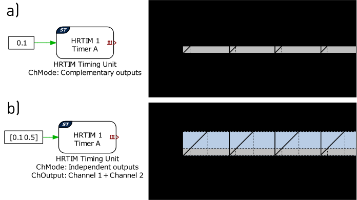
Fig. 18 HRTIM timing unit output modes: a) complementary PWM pair, b) two independent PWM outputs
The figure below shows two HRTIM timing units (A and B) that are Self synchronized. Each HRTIM timing unit has its own carrier frequency and compare value. There is no synchronization signal between the two timing units and the relative position between the carriers is not deterministic.
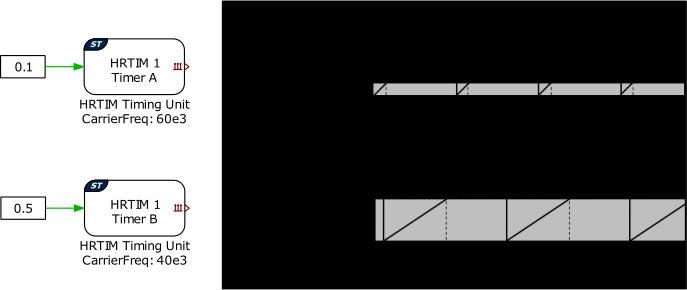
Fig. 19 Two independent HRTIM timing units (Self synchronized)
The following figure shows two HRTIM timing units (A and B) that are synchronized to a common HRTIM Master block. The HRTIM timing units A and B inherit the carrier frequency from the master timer. The master timer generates a synchronization signal for each of the two timing units and the relative position of the carriers of the timing units and the master timer is given by the \(ph\) input terminal. At each synchronization edge from the master the synchronized timing units are reset and the counter restarts at zero. Timing units can be phase-shifted arbitrarily with respect to the master carrier. Up to four different phase shifts can be introduced, with each phase shift applying to one or multiple timing units. It is possible to synchronize additional timing units with zero phase shift to the same master timer.
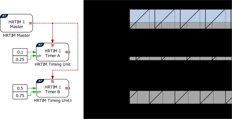
Fig. 20 Two HRTIM timing units synchronized to a HRTIM Master block
The HRTIM timing unit block can configure interrupts to trigger the ADC start-of-conversion and the Control Task Trigger. Interrupts are synchronized with the PWM carrier, and the repetition counter period determines how many events need to occur before a trigger is generated, as shown in the figure below. When the carrier type is symmetrical, for even values of repetition counter period, the interrupts will occur at the carrier underflow or overflow events. Underflow and overflow events correspond to PWM carrier reaching the respective carrier minimum or carrier maximum values. When the carrier type is sawtooth, the ADC trigger can occur at the period event or in the middle of the relative on-time of the PWM output. This allows to have ripple free ADC conversions. The Control Task trigger for a sawtooth carrier will always occur at the period event of the carrier.
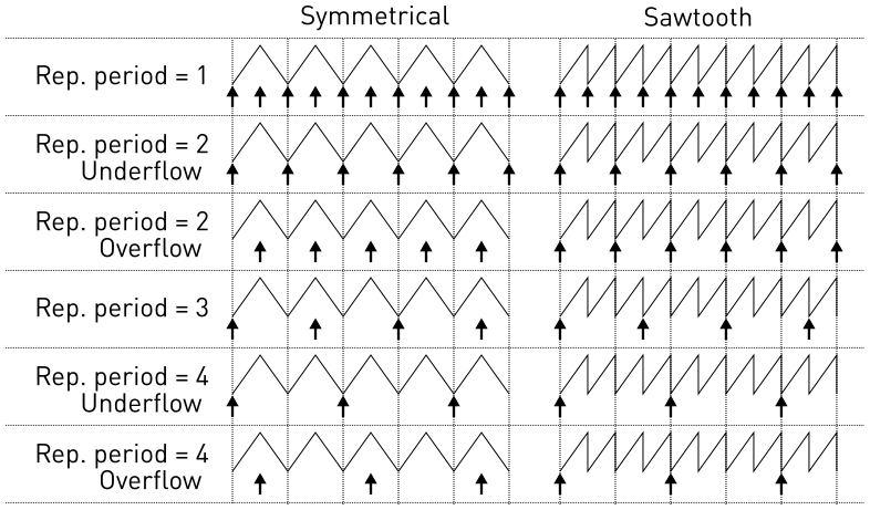
Fig. 21 Trigger events based on the repetition counter period
The figure below shows an example of a symmetric PWM carrier with the repetition counter period set to \(2\), the trigger event set to overflow, and the polarity configured with an active state logic of 1.
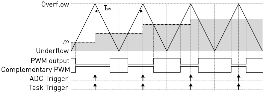
Fig. 22 PWM and trigger schemes for symmetric carrier
The following figure illustrates an example of a sawtooth PWM carrier with the repetition counter period set to \(1\). The ADC trigger event is set to Midpoint, and the polarity configured with an active state logic of 1. The sampling point is adjusted in such a way, that it will always occur in the middle of the relative on-time. This can lead to a varying base task period if the timing unit generates the Control Task trigger, especially during transient operation.
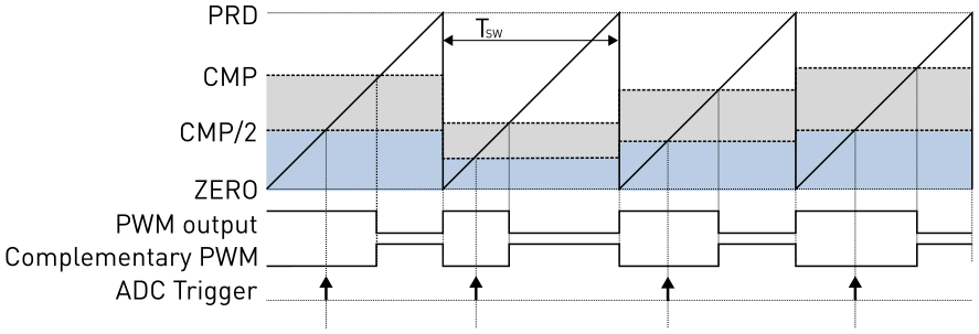
Fig. 23 Midpoint sampling for sawtooth carrier, the sampling point is continuously adjusted to be in the middle of the compare value
Configure the Frequency variation parameter to enable the frequency input port \(f'\). The resulting carrier frequency \(f_\mathrm{c}\) is calculated as the product of the nominal carrier frequency specified in the block parameter Carrier frequency and the input signal \(f'\).
Note
The HRTIM Timing Unit block employs preload and shadow registers to manage updates to the period and modulation index. When the CPU writes a new period or modulation index value, it is first stored in a preload register. The value is then transferred to the shadow register when an update event occurs.
The event that performs this transfer is the same event that is used to trigger the base task and is configured in the Trigger tab. It typically occurs at the end of a period or in the middle of a period and can be downsampled by a repetition counter. The HRTIM peripheral uses the values stored in the shadow register, ensuring that the period update takes effect only at the defined updated event.
Note
If the task scheduler detects a CPU overflow and the model contains a Powerstage Protection target block, all HRTIM Timing Unit outputs are switched to the passive state.
Parameters
Main
- HRTIM unit
Selects the HRTIM unit to use. There are two HRTIM units available.
- Timing unit
Selects the HRTIM timing unit of the output channel. Each timing unit can independently generate up to two independent PWM outputs or a complementary PWM pair. HRTIM timing unit
Fis not available on chips of the F3 target family.- Synchronization
If set to
Self, the HRTIM Timing Unit is independent of all other HRTIM blocks.If set to
Master, an HRTIM Master block must provide a synchronization signal to the HRTIM Timing Unit. Synchronizing HRTIM Timing Units to an HRTIM Master enables the introducteion of phase shifts between different HRTIM Timing Units and enables burst mode control.If set to
External, the HRTIM Timing Unit can be synchronized to an external synchronization signal using an External Sync block. If the Synchronization behavior of the External Sync block is set toStart and reset on sync, the frequency of the PWM signal generated by the HRTIM Timing Unit can be synchronous to the external synchronization signal independent of the system clock frequency. If Carrier type is set toSawtooth, the Carrier frequency \(f_\mathrm{HRTIM}\) needs to be lower than the frquency of the external synchronization signal, \(f_\mathrm{EXT}\), to ensure that the HRTIM Timing Unit counter does not reach its period value and reset before the reset signal from the external synchronization signal occurs. As a consequence of this, the \(duty cycle\) needs to be scaled by \(\frac{f_\mathrm{HRTIM}}{f_\mathrm{EXT}}\). If Carrier type is set toSymmetrical, the frequency of the HRTIM Timing Unit must be an integer multiple of the frequency of the external synchronization signal.A special case occurs if the HRTIM Timing Unit is synchronized to an HRTIM Master block which is itself synchronized to an External Sync block with Synchronization behavior set to
Start and reset on sync. This setup is only allowed if Phase shift is set toEnabledon the HRTIM Timing Unit. If Carrier type is set toSymmetrical, only a phase shift of \(0\) is allowed and the Carrier frequency of the HRTIM Master must be equal to or an integer multiple of the frequency of the external synchronization signal. If Carrier type is set toSawtooth, any phase shift is allowed, but the following condition must be satisfied:\[1 - \frac{f_\mathrm{EXT}}{f_\mathrm{HRTIM}} < phase < \frac{f_\mathrm{HRTIM}}{f_\mathrm{EXT}},\]where \(f_\mathrm{HRTIM}\) is the Carrier frequency of the HRTIM Master, and \(f_\mathrm{EXT}\) is the frequency of the external synchronization signal. Both the \(phase\) and the \(duty cycle\) need to be scaled by \(\frac{f_\mathrm{HRTIM}}{f_\mathrm{EXT}}\).
- Carrier type
Selects the carrier waveform, either sawtooth or symmetrical.
- Carrier frequency
Defines the frequency of the carrier in hertz \((\mathrm{Hz})\). This option is only visible if the HRTIM timing unit is
Selfsynchronized. If the timing unit is synchronized toMasterthe timing unit will inherit the carrier frequency of the HRTIM master.- Frequency tolerance
Specifies the behavior when the desired carrier frequency is not achievable based on the system clock frequency.
- Frequency variation
Enables or disables the frequency input port \(f'\). This option is only selectable if the Synchronization parameter is set to
Self.- Variable frequency lower limit
The HRTIM prescaler is configured during MCU initialization and cannot be modified during operation. To prevent saturation of the period register during runtime, a lower bound must be defined for the operating range of the input to the frequency variation inport
f'. It is defined per unit \((\mathrm{pu})\) of the nominal frequency. This lower bound is used to select the HRTIM prescaler and defines the frequency range guaranteed during operation. The minimum achievable frequency during operation may be lower than this bound, as it is determined by the selected prescaler.- Phase shift
Enables or disables the phase shift input port \(ph\). This option is only visible if the HRTIM timing unit is synchronized to
Master.- Enable port
An additional component port is created if Enable port is set to
Show. Applying a signal \(= 0\) to this port sets the HRTIM timing unit outputs to the idle state.
Channel
- Mode
Configures the output PWM channels to operate independently from each other or act as complementary signals. Each HRTIM unit can generate up to two independent PWM outputs or one complementary PWM pair.
- Output signals
Defines which output channel should generate PWM signals. If
Channel 1 + Channel 2is selected, two duty cycle values and enable signals (if the Enable port is set toShow) are expected at the respective input terminals. The two independent PWM signals share the same carrier frequency and phase shift. This parameter is only visible if Mode is set toIndependent outputs.- Polarity
Defines the logical output of the PWM output when an active state is detected.
- Blanking time
Delay between the rising and falling edges of a complementary PWM output pair in seconds \((\mathrm{s})\). This parameter is only visible if Mode is set to
Complementary outputs.- Idle state
Defines the level of the output signal when the output is in its idle state. An output channel enters the idle state if it is disabled due to an enable signal \(=0\), the en input of the Powerstage Protection block or if it reacts to the burst mode controller.
Activeandinactivelevels change in function of Polarity.
Trigger
- ADC trigger
Enables or disables the ADC start-of-conversion trigger.
- ADC trigger event
Selects the ADC trigger event. This parameter is only visible for a carrier of type
sawtooth. WhenMidpointis selected the ADC start-of-conversion is started in the middle of the relative on-time of the PWM signal. If set toPeriodthe ADC trigger event occurs at the overflow event of the sawtooth carrier. Please note the the Timing unit E cannot generate a period trigger event.- Task trigger
Enables or disables the Control Task Trigger. For a
sawtoothcarrier the task trigger is generated at the period event of the counter.- Repetition counter period
Determines how many events need to occur before a trigger is generated.
- Trigger event
Selects the trigger event. This parameter is only visible for a carrier of type
symmetrical. When the carrier type is symmetrical, for even values of repetition counter period, the interrupts will occur at the carrier underflow or overflow events. Underflow and overflow events correspond to PWM carrier reaching the respective carrier minimum or carrier maximum values.
Burst Mode
- Burst mode
If set to
Enabledthe HRTIM timing unit output channels will react to the burst mode control signal emitted by the HRTIM Master block. If set toDisabledthe timing unit will ignore the burst mode controller. This option is only selectable if Synchronization is set toMaster.
Protection
- Channel fault state
Defines the level of the output signal when the output is in its fault state. An output channel enters the fault state if an Analog protection signal trips.
Activeandinactivelevels change in function of Polarity. If set tohigh impedancethe outputs will be floating in a high impedance state.