Half Bridges (Low-/High-Side Connected)
Purpose
Series-connected half-bridge inverter with a Sub-cycle average implementation
Library
Electrical / Power Modules
Description
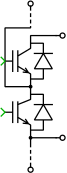
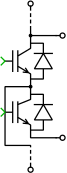
These Power Modules implement multiple series-connected inverter cells for use in modular multilevel converters. All control signals as well as the DC side terminals are vectorized with their width matching the number of cells.
The component offers two configurations:
Sub-cycle averageEach gate input is controlled by a floating-point number with values between \(0\) and \(1\), representing the relative on-time of the corresponding semiconductor over one simulation step, as described in Sub-cycle Averaging. The DC side of the converter has current source behavior and must be connected to a positively biased capacitor or voltage source. The AC side is typically connected to an inductor.
In
Sub-cycle averageconfiguration, C code generated from this component is suitable for real-time simulations on the RT Box, where it is executed on the CPU or FlexArray solver. In this case, connect the gate inputs to PWM Capture blocks from the RT Box component library.SwitchedThe power semiconductors are modelled as ideal switches controlled by instantaneous logical gate signals. A switch is turned on when the corresponding gate signal is
non-zero. For compatibility with theSub-cycle averageconfiguration it is recommended to use the value \(1\) for non-zero gate signals.The
Switchedconfiguration is not recommended for real-time simulations on the RT Box. It is intended for offline simulations that resolve each individual switching event and can serve as a reference for results obtained with theSub-cycle averageconfiguration.
Note
In Sub-cycle average configuration, the primary (DC) sides of the inverter cells must remain galvanically isolated from each other.
Note
The voltage sources connected to the converter must not be short-circuited. Therefore, combinations of switching signals that cause shoot-through of DC links are not permitted. The corresponding restrictions are described under the Assertions parameter. Additionally, DC voltages across diodes must not be negative, as DC voltage clamping through diodes is not permitted.
Parameters
- Configuration
Selects the component configuration. See the descriptions of
Sub-cycle averageandSwitchedabove.- Semiconductor symbol
Use this setting to choose between
IGBTandMOSFETfor the symbol of the active semiconductor switches. This setting only affects the schematic representation and does not change the electrical behavior of the component.- Number of cells
Number of series-connected half-bridge inverters.
- Assertions
If the Configuration is set to
Sub-cycle averageand this parameter is set toon, the block checks the duty-cycle gate input signals for overlapping relative on-times. It issues aHalf-bridge shoot-througherror if the following condition is met:The sum of the gate signals for the upper and lower switches of the same half-bridge exceeds \(1\).
- Switch model (CPU code generation)
If the Configuration is set to
Sub-cycle average, this parameter selects the switch model when CPU code is generated.